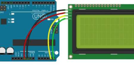
LCD1602 I2C 位置定義說明
The I2C address of the module
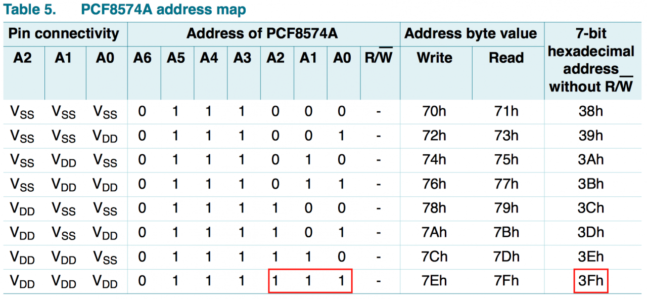
As indicated in the datasheet, the default I2C device address of PCF8574A is 0x3F:
and the address of PCF8574 is 0x27:
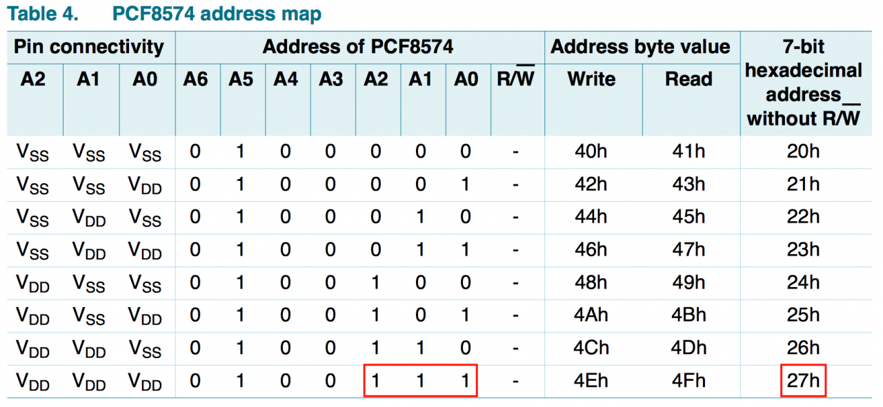
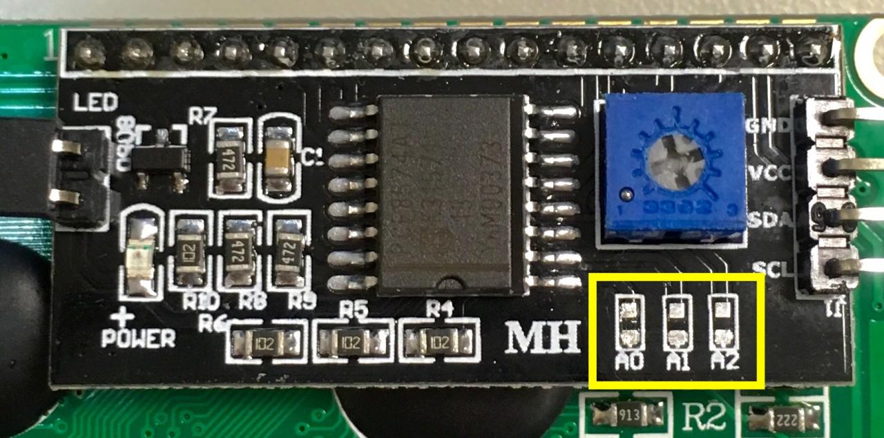
For the library, the 7-bit I2C address format is used so that’s why we assign 0x3F / 0x27 as the address for the device. However, the module also provides flexibilities for developers to customize the address to prevent from address collision on the same I2C bus. This is achieved by short-circuiting the A0 / A1 / A2 pads indicated by the yellow rectangle below:
The address bits (A0 / A1 / A2) of the PCF8574A / PCF8574 are controlled by the A0 / A1 / A2 pins on the chip and it’s pulled high on the module by default. The schematic diagram is:
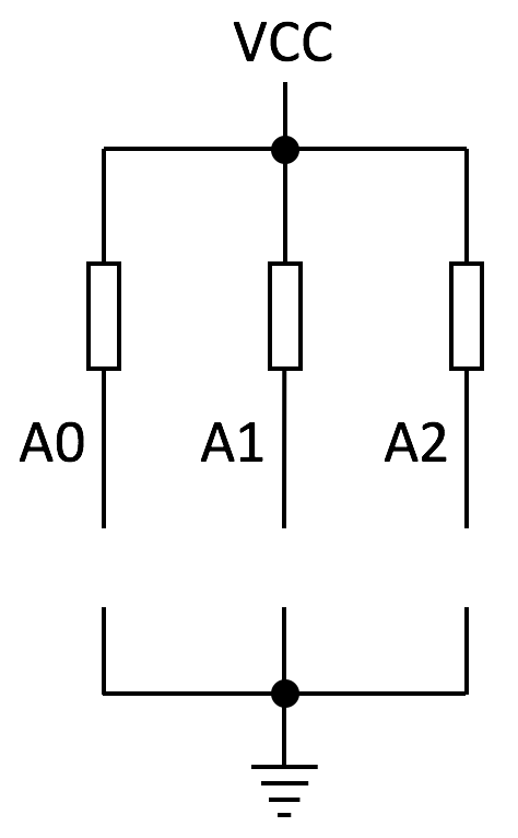
Therefore, if you mount a 0R resistor on the A0 pads of the module, for example, it will make the A0 bit to 0 and this changes the I2C address of this device from 0x3F to 0x3E on PCF8574A (or from 0x27 to 0x26 on PCF8574) according to the address map listed above. By following the same idea, you can modify the address bit A1 and A2 in the same way to customize your own I2C device address.